I2C Expander
Make sure to use lox.begin after each time you call a new device.
include "Wire.h"
extern "C" {
include "utility/twi.h"  // from Wire library, so we can do bus scanning
}
include "Adafruit_VL53L0X.h"
Adafruit_VL53L0X lox = Adafruit_VL53L0X();
define TCAADDR 0x70
void tcaselect(uint8_t i) {
  if (i > 7) return;
  Wire.beginTransmission(TCAADDR);
  Wire.write(1 << i);
  Wire.endTransmission();
}
// standard Arduino setup()
void setup()
{
  while (!Serial);
  delay(1);
  Serial.begin(115200);
  Serial.println(F("VL53L0X API Simple Ranging example\n\n"));
  Serial.println("\nTCAScanner ready!");
  Wire.begin();
  for (uint8_t t = 0; t < 8; t++) {
    tcaselect(t);
    Serial.print("TCA Port #"); Serial.println(t);
    for (uint8_t addr = 0; addr <= 127; addr++) {
      if (addr == TCAADDR) continue;
      uint8_t data;
      if (! twi_writeTo(addr, &data, 0, 1, 1)) {
        Serial.print("Found I2C 0x");  Serial.println(addr, HEX);
      }
    }
  }
  Serial.println("\ndone");
}
void loop()
{
  for (uint8_t x = 1; x < 5; x++) {
    tcaselect(x);
    if (!lox.begin()) {
      Serial.println(F("Failed to boot VL53L0X"));
      while (1);
    }
    VL53L0X_RangingMeasurementData_t measure;
    //Serial.print("Reading a measurement... ");
    lox.rangingTest(&measure, false); // pass in 'true' to get debug data printout!
    if (measure.RangeStatus != 4) {  // phase failures have incorrect data
      Serial.print("sensor "); Serial.print(x);
      Serial.print(" Distance (mm): "); Serial.println(measure.RangeMilliMeter);
    } else {
      Serial.println(" out of range ");
    }
  }
}
CLI RPI PROGRAMMING
DEBOUNCE BUTTONS
Add a second button and modify your code from exercise three so that the LED turns off when the second button is pressed.
TEACHER CHECK ____
Modify your code use a single button to turn on and off the LED.
Add a pin toggle to your code again so that the LED changes state after each press of the button. NOTE: This may not work as expected.
Connect your scope to monitor the button press on channel one and the output to the LED on channel two.
Press the button and look at the results on the scope.
What might be causing the unpredictable behavior of your circuit?
What can you do in code to fix this problem?
TEACHER CHECK ____
BASIC COMMAND LINE
Overview
You will be using cmder to run command line operations.
Command Overview
The following are a list of seven commands that you can used to get started with using the command line. Note that the λ represents the command prompt of your shell and you will not type this when entering commands. Command prompts vary by shell and include # $ >> λ
List the contents of a directory: Use the ls command to list the contents of any directory.
Λ ls
Make a directory: Use the mkdir command to create a new directory.
Λ mkdir directoryname
Change directory (down)
Λ cd directoryname
Change directory (up)
Λ cd ..
Show directory path: Use the pwd command to show your present directory path.
Λ pwd
Edit a file
Λ nano newfile.txt
Delete file
Λ rm newfile.txt
Exercise
Open cmder and test out the above commands.
Create Code Directory
In this lesson you will create a new directory for storing your code. Note that when you first open cmder you should find yourself in the following directory.
C:\Users\Student
λ
Exercise
Create a directory called “Code” under C:\Users\Student
Confirm the existence of your new directory using the Windows Explorer
TEACHER CHECK ____
Set IDE Path
In this lesson, you will set the path of your Arduino IDE so that it stores your code the directory you just created.
Exercise
Select File/Preferences in your Arduino IDE
Under Sketchbook Location browse to find the directory you just created in the step above.
Press okay
TEACHER CHECK ____
}
PYTHON GUI
https://docs.python.org/2/library/tkinter.html#a-simple-hello-world-program
https://www.python-course.eu/tkinter_layout_management.php
TOF VL53L0X SENSOR
Overview
In this lesson, you will learn how to setup and use a VL53L0X time of flight (TOF) sensor to measure distance.
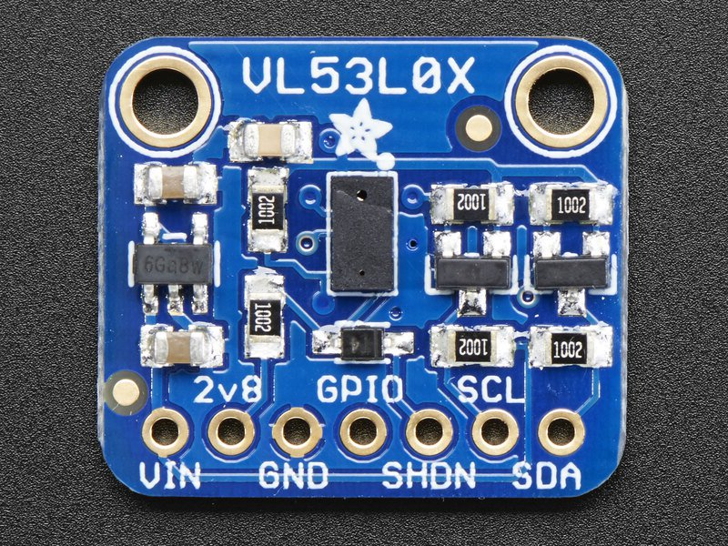
Wiring
Above is a picture of the VL53L0X module. Wire the module as follows.
GND pins to ground.
VIN pin to 5 volts
SCL pin to A5 on your Arduino or Metro
SDA pin to A4 on your Arduino or Metro
Initial Test
Follow the instructions below to test that you have wired your module correctly.
Install the VL53L0X library from Adafruit on your Arduino IDE.
Open the vl53l0x project from Examples.
Download the code to your board.
Open your terminal window.
Note that the code runs at 115200 so you will need to set this baud rate in the terminal window. You should see:
Adafruit VL53L0X test
VL53L0X API Simple Ranging example
…and then a set of distance readings in mm.
Range Testing
The following code should provide feedback if the object being measured is between 50mm and 100mm from the sensor.
#include “Adafruit_VL53L0X.h”
Adafruit_VL53L0X lox = Adafruit_VL53L0X();
int dist;
void setup() {
Serial.begin(115200);
lox.begin();
}
void loop() {
VL53L0X_RangingMeasurementData_t measure;
lox.rangingTest(&measure, false);
dist = measure.RangeMilliMeter;
if ((dist < 100) && (dist > 50))
Serial.print(“In the zone: “);
Serial.println(dist);
delay(100);
}