Programming Leds
Overview
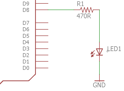
LEDs are a good example of the kinds of devices you can drive with a microcontroller. LEDs also provide an easy way to indicate if a microcontroller pin is set to HIGH or LOW. IMPORTANT: You MUST remember to use a resistor in series with any LED to prevent the LED from burning out. Driving too much current through and LED will damage the LED and potentially the microcontroller.
Exercise:
Follow the schematic below to connect an LED to pin 8 of your microcontroller. Note that this is a suggested circuit for controlling an LED from your microcontroller. On your breadboard, you might find it more convenient to reverse the order of the LED and resistor.
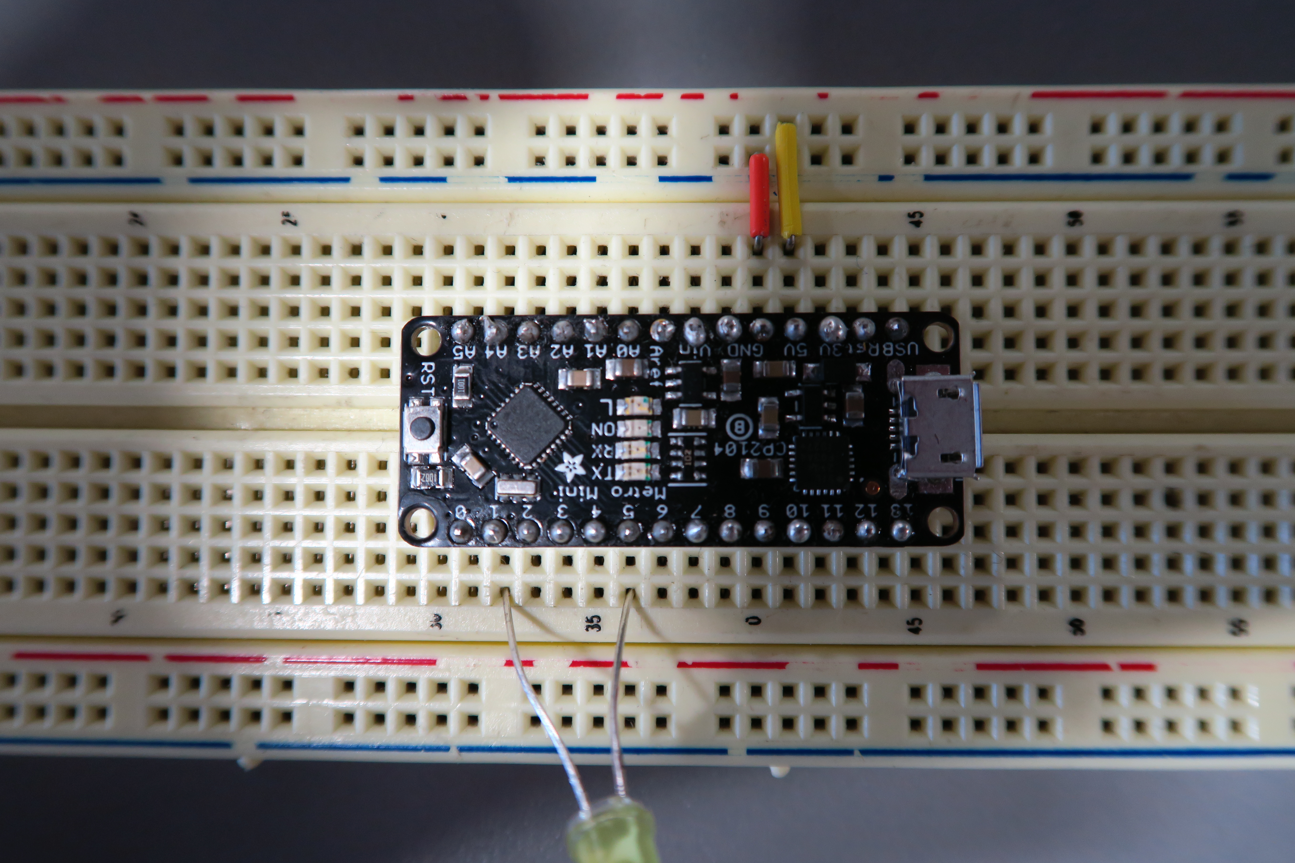
IMPORTANT: Each pin on the microcontroller should only be used as you intend to use it. In the image below, the user is intending to control the LED with pin 5, but has inadvertently connected the other lead of the LED to pin 2.
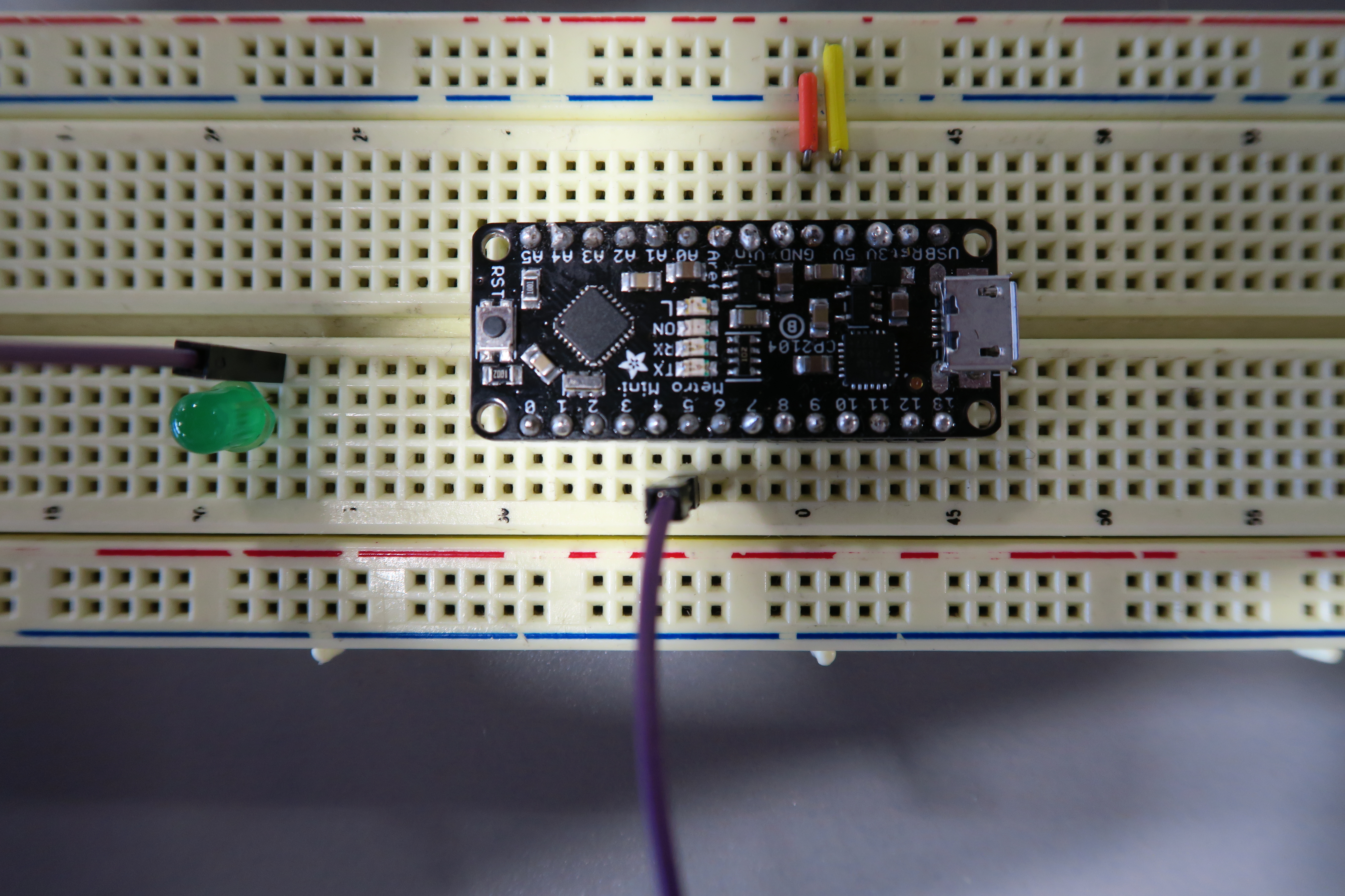
In the correct example below, the user has used a jump wire to connect the LED, so that only pin 5 is being used.
TEACHER CHECK _____
Write a program to turn on the LED.
Set the pin you are using to control the LED as an output pin.
Use digitalWrite to drive the pin to 5V.
TEACHER CHECK _____
Modify your program to turn off the LED.
Change the LED to a different pin and turn it on. You may use any of the digital pins (0 - 13).
IMPORTANT NOTE: You should generally avoid using digital pins 0 and 1 as either inputs or outputs. Using these pins might interfere with the programming of your device.
Add two more LEDs to two additional pins on your microcontroller and turn them all on.
TEACHER CHECK _____