Keypad And Code
Overview
In this lesson you will you use your knowledge of keypads and arrays to make keypad security software.
Exercise:
Write a program to read and display key presses on the serial monitor.
NOTE: It is important that you setup your array as a char. For example:
char nameofarray[3];
TEACHER CHECK ____
Exercise:
Write a program to read each key press and store the key that was pressed into an array. The first key pressed should be stored in the 0 index of the array and the second key pressed should be stored in the 1 index of the array and so on for a total of five key presses.
After five keys are pressed it should display all of the elements of the array. (see your code from above for displaying elements of an array)
TEACHER CHECK ____
Exercise:
Modify your code from above to display the count of the key presses in addition i.e. after one key is pressed it should display one and so on.
TEACHER CHECK ____
Exercise:
Modify your code from above so that it stops after the user presses the button five times and displays “Done.”
TEACHER CHECK ____
Challenge:
Modify your code so that it compares the five keys the user presses with five keys stored in an array. If the each of the five keys pressed matches each of the five keys stored in the array, in the correct order, display “Open” otherwise display “Error”.
TEACHER CHECK ____
IR REMOTE CONTROL
Overview
Infrared remotes are commonly used to control consumer audio and video devices. They can also be used for cameras and household appliances such as air conditioners. Unlike the previous user interface devices you have learned about, remotes are not physically connected to the device they are controlling. In the case of IR remotes they communicate with the device by using a signal composed of infrared light.

IR Circuit
In order to convert the infrared light signal into a digital voltage signal that your MCU can read you will need to use an IR receiver.

Exercise
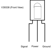
The IR receiver you are going to use is V39338 made by Vishay and will be provided by your teacher. There are many versions of IR receivers and most work similarly to this device though may have a different order of pins.
Using the diagram below (IMPORTANT) connect the power and ground pins of the device.
Connect the signal pin to your oscilloscope and record the default value of the signal pin.
Default voltage level: ___________
Press a button your IR remote and note if there is any change on your scope.
Adjust your scope settings so that you can see pulses when you press a button on your IR remote. If you are having trouble seeing the signal set the time/div dial to 5ms.
Decoding IR Signals
The signals produced by IR remotes are fairly complex but not impossible to decode with the use of your oscilloscope. Each remote corresponds to a specific transmission protocol such as NEC, Sony SIRC and Philips RC5. The remote used in this project uses the NEC protocol.
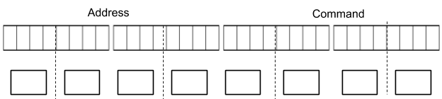
The signal is made up of four components: a start pulse, a space, an address (16-bit), and a command (16-bit). Within the address and command parts of the signal a zero is represented as a short low pulse and a one is represented as a long low pulse.

Exercise
Using your oscilloscope make the following measurements. Make sure to include the correct units.
Start = __________
Space = __________
Zero = __________
One = __________
TEACHER CHECK ____
IR Remote Code
Follow the steps provided below to install and use the example IRrecvDemo code. Using this code your microcontroller can capture the signal from your IR receiver, convert the pulses into numbers and print these numbers on your serial monitor.
Exercise:
Open the IRrecvDemo code which should be be found in your Examples/IRremote. The IRremote directory should be found at the bottom of the examples menu under Examples from Custom Libraries. If you cannot find this directory you must install it using the manager libraries option. The file you want to install is called IRremote by Shirriff.
Connect the signal pin of your IR receiver to the correct pin on your microcontroller. This pin number is listed at the top of the IRrecvDemo code. Note: You cannot use another pin with this code.
Download the code and use your remote to display values in the Serial Monitor. Note that these values are displayed in hex.
Write down the hex values for the following buttons.
Button Press |
Hex Value |
1 |
|
2 |
|
3 |
|
“right arrow” |
|
VOL- |
TEACHER CHECK ____
Hex Values
Using your scope decode the signal for button 1 and confirm that this matches the decoded signal provided by the code.
Exercise:
Capture the signal for button 1 on your oscilloscope.
Record both the 16-bit address and 16-bit command in the top row of boxes provided below. Make sure to correctly identify which pulses are ones and which pulses are zeros.
Convert the value in binary to a value in hex and place the hex value in bottom row of boxes.
Compare the hex value you measured on the scope with the hex value you received in your serial monitor.
Value from oscilloscope: ________________________
Value from Serial Monitor: ________________________
TEACHER CHECK ____
Remote Control
Using what you have learned so far you can now use your remote control to control any device on your breadboard.
Exercise
Add an LED to your breadboard and modify your code so that when a user presses the button 1 the LED turns on and when the user press the button 2 the LED turns off.
TEACHER CHECK ____