Rules for Schematics
Overview
Once you have finished the tutorials, you are ready to design your circuit using Fusion 360. Follow the steps below when designing your schematics.
Complete Breadboard: Make sure the breadboard version of your circuit includes all of the parts you need including power and is working correctly. Do not add anything to your Eagle circuit that you have not already testing on your breadboard.
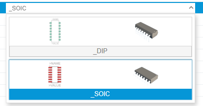
Adding Parts: Make sure to only select through-hole parts (not surface mount) for all of your components. Note the part with green pads is through-hole. The part with red pads is surface mount.
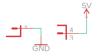
Power and Ground: Make sure to include power and ground symbols on your on your schematic. Make sure your power symbols face up and your ground symbols face down.
Mirror Design: Make sure your schematic mirrors exactly the connections on your breadboard.
Crossed Wires: Where ever possible avoid crossing lines on your schematic.
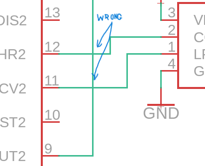
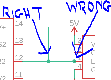
Right Angles: Make sure all your wires on your schematic run at right angles. NOT like the example below.
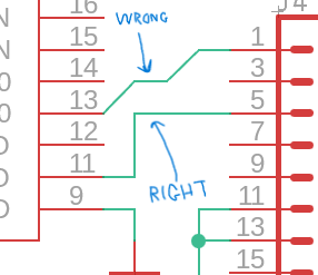
Junctions: Junctions should only exist between two connected wires. Never on a single wire or at a pin.
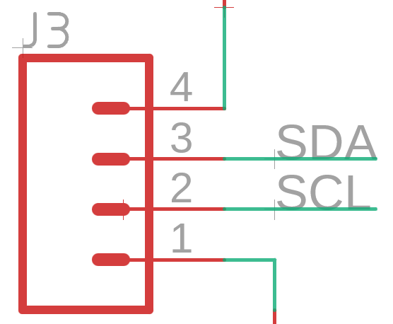
Labels: Label all signal wires with names that describe their function.
ERC: Make sure to run an ERC (electronic rule check) before finalizing your schematic.