L293D
Overview
The L293D or similar SN764410NE is a complete motor driver ICs. The L293D is dual motor drivers meaning that each IC can drive two motors. They are designed to handle about 600 mA per motor.
Below is a simple hook up diagram for the L293D. It is imporant to note that there are two connections for power. One is Vbat and the other is Vcc. This is because the your motor should be powered by a different voltage from your logic (microcontroller, sensors, etc). Vcc is the logic voltage or 5 Volts. Vbat is the input for the voltage you will use to control your motor. IMPORTANT: You should NOT drive your motor using Vcc or the same supply as you are using for your logic.
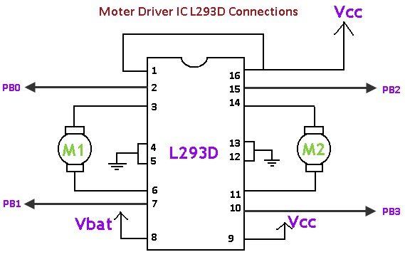
There are two inputs for controlling each motor. Pins PB0 and PB1 are for controlling the motor on the left and pins PB2 and PB3 are for controlling the motor on the right. Below is a table showing how the control lines drive each motor.
PB0 |
PB1 |
Function |
HIGH |
HIGH |
Brake |
HIGH |
LOW |
Turn Clockwise |
LOW |
HIGH |
Turn Counter-Clockwise |
LOW |
LOW |
Brake |
Exercise:
Set up the L293D (or SN745510NE) to drive a single motor in two directions. You should NOT use a microcontroller to complete this first exercise. (i.e. just set the inputs into power and ground)
Add a microcontroller (Arduino) to control the motors.
TEACHER CHECK ____