Breadboard Conventions
Overview
The following are good conventions for setting up your breadboard and adding components. You do not have to complete these steps, just read the guide and ask questions if anything does not make sense.
Good Practices
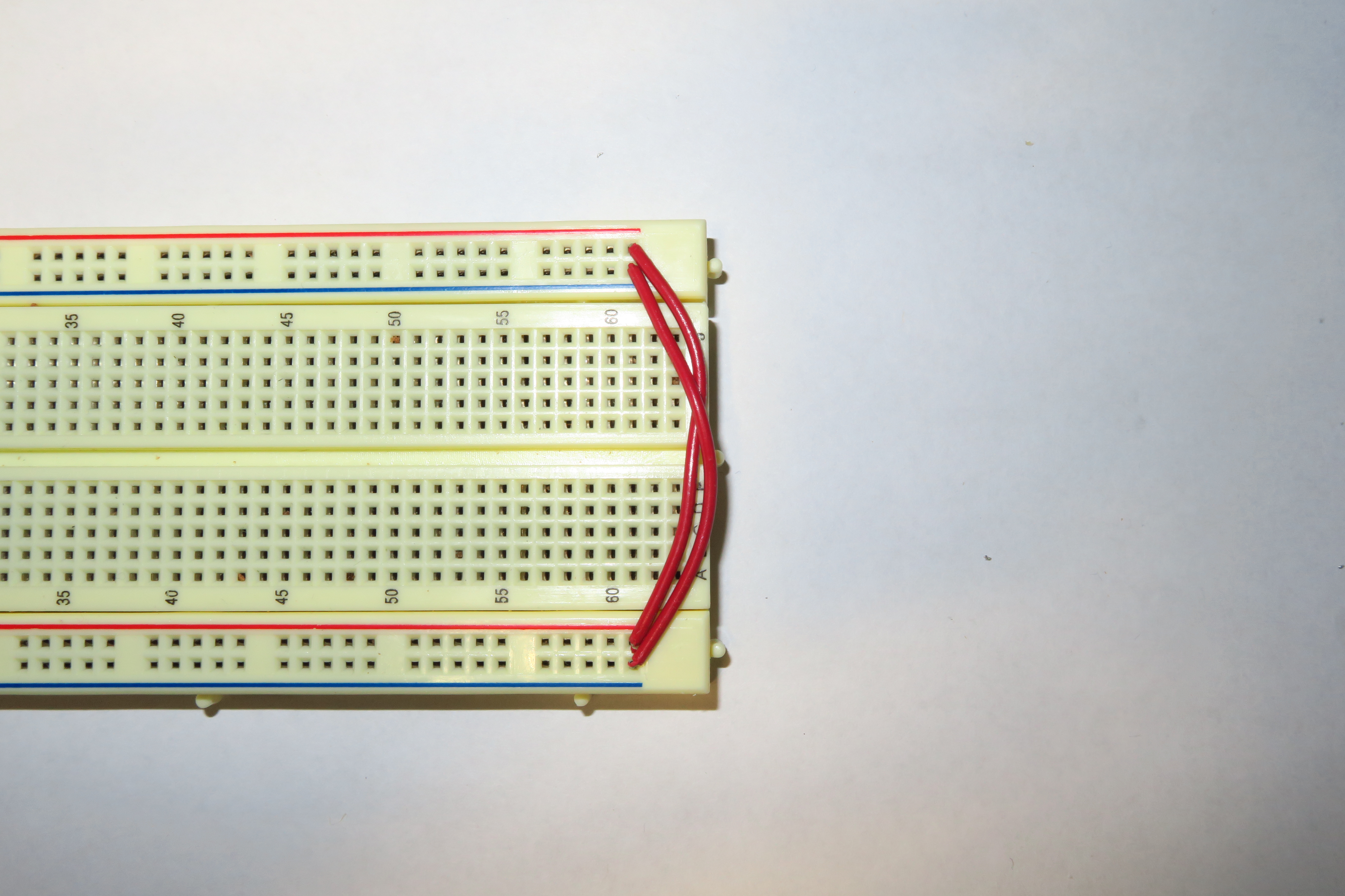
Power buses and ground buses are connected. As mentioned in the previous lesson, the two ground buses (and the two power buses) are not connected inside the breadboard. In order to connect these two buses you must use jump wires as shown below. IMPORTANT: Make sure only power to power and ground to ground. Do not cross connect these buses.
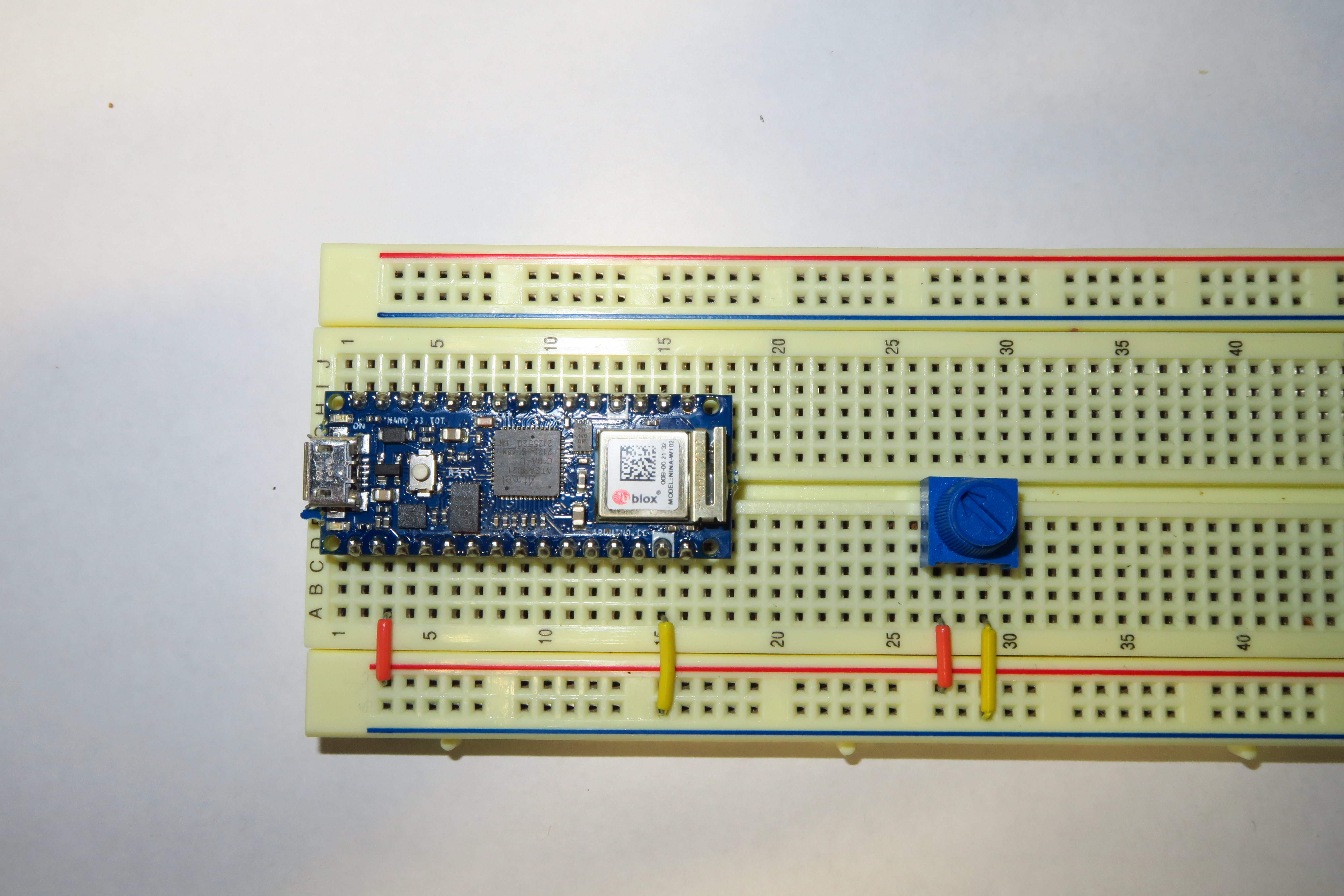
Connections to power and ground are made with short orange and yellow jump wires. Using these wires will make your board less cluttered and will make it very easy to identify which pins and leads are connected to power and ground. Below is an image showing an integrated circuit and potentiometer both with connections to power and ground.
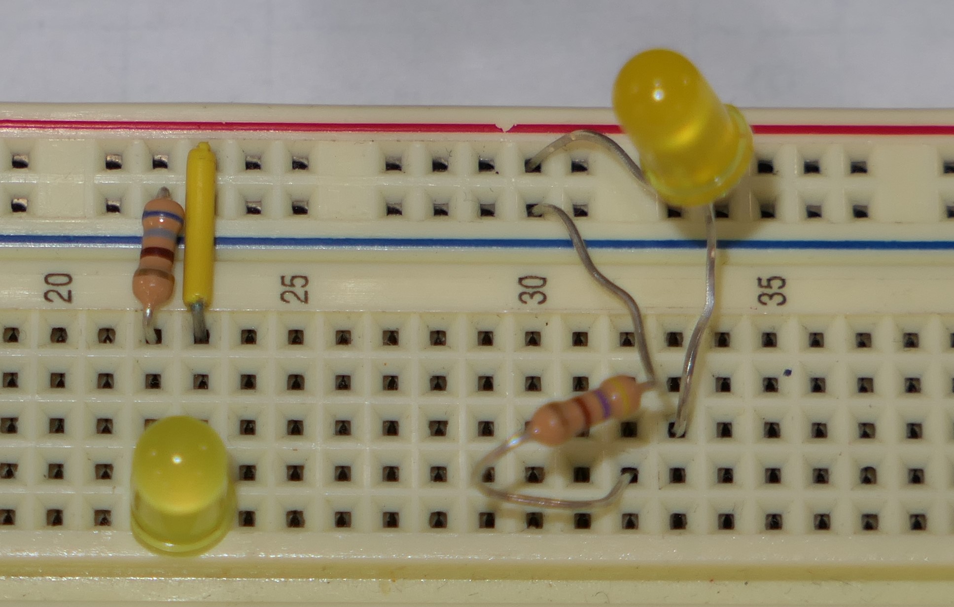
Long componet leads are cut short to fit snug against the breadboard. Resistors, LEDs and capacitors are shipped with very long leads which can get very messy on your breadboard and potentially cause short circuits. The photo below shows to contrasting circuits. The one on the left is neat and reliable. The one of the left is likely to cause problems in your circuit.
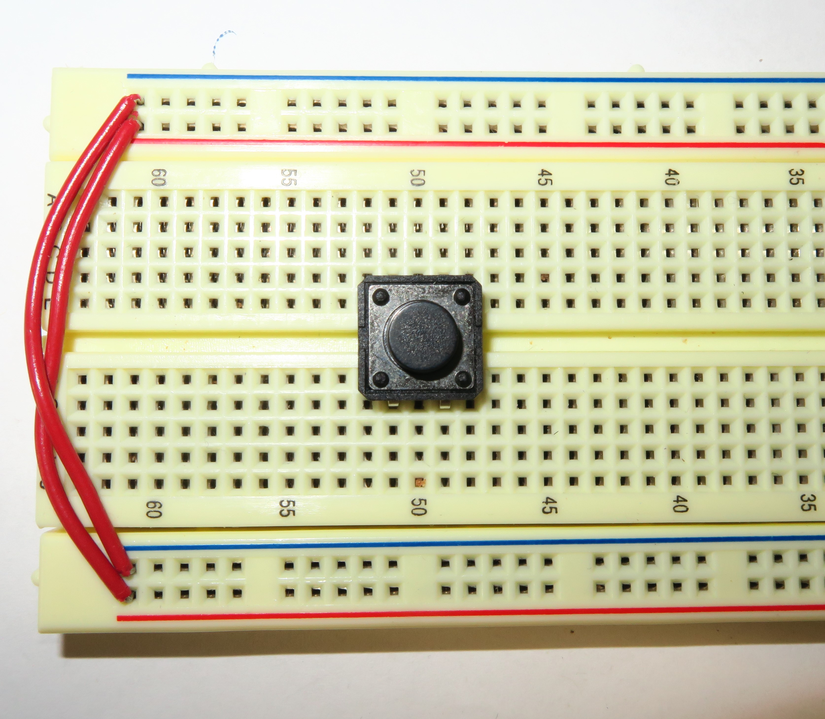
Buttons across the center of the breadboard. This will make your design neater and avoid short circuits.
Exercise:
Following the recommendations above, set up an LED on your breadboard with a button to turn it on and off. You can consult a previous schematic if that is helpful.
TEACHER CHECK _____