Simple Circuit
Overview
In this first lesson, you will light an LED using just an LED, a resistor, test leads and your bench power supply. This lesson is as much about lighting an LED as it is about learning to experiment and not be afraid to make mistakes. In this lesson, you will not be told exactly how to make the LED light. Engineering is primarily about experimenting and it is hard to experiment without making mistakes. Below you will find a description of each of the components as well as a schematic for the circuit.
Exercise:
Use the following components and tools to light an LED.
LED: LED stands for light emitting diode and is the most common lighting device available today. There are many different shapes, sizes and colors of LEDs. The ones you will be working with today look like the following. Note that LEDs are polarized. This means they only work in one direction.

Resistor: Resistors are used to limit the current in a circuit. It is important to use a resistor when lighting an LED so that the LED does not receive too much current and break. Resistor values are measured in Ohms. Smaller values represent lower resistance and larger values represent higher resistance. You will need a resistor with a value between 220 Ohms and 1000 (1K) Ohms. Below is an image of the type of resistor you will use in this first circuit. Note that the color bands are used to represent the resistance values.

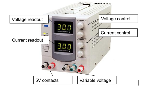
Bench Supply: A bench supply is used to supply power to your circuits. In order to use this power, you will need to connect leads (described below) to the black and red binding posts shown on the bench supply below. Note that this bench supply has two sets of binding posts. This is because it can supply two different voltages at the same time. The black and red pair on the left provide a fixed 5 volts. The pair on the right provide a variable voltage from 0 to 30 volts.
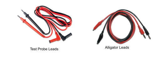
Test Leads: Test leads are used to connect the voltage from your bench supply to your circuit. To supply power to your circuit you will need to use a pair of test leads connected to either pair (if your bench supply has two voltages) of black and red binding posts on your bench supply. The black lead (ground) connects to the black binding post and the red lead (power) connects to the red binding post. Note there are two types of test leads. For this first lesson you will use the ones labeled alligator leads.
Exercise:
Using your bench supply for power try to connect the resistor and LED in such a way that the LED is lit. It will take some experimentation. It is possible to destroy the LED if you power it without the resistor or it is not connected correctly, but again that is the price of experimentation. It is also possible that some of the LEDs are already broken. Try working with a few until you get one to light.
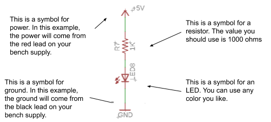
Below is a schematic for a circuit that will light an LED. A schematic is a symbolic representation of the circuit. You will learn more about these in future lessons, but for now see if you can decipher the symbols and use this as a guide.
TEACHER CHECK _____
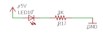
Once you have the LED lit, try to change the order of components as described in the schematic below. Note that the only difference between the two schematics is that in the one below the LED is connected directly to power. Do you notice any difference in the function of the circuit?
TEACHER CHECK _____
Reverse the direction of the LED in the circuit. Does the LED still light? The LED should only work in one direction. Because of this feature, we call an LED a polarized device (as mentioned above). Try to identify a feature on the LED that signifies which direction it should be facing in the circuit.
TEACHER CHECK _____
Reverse the direction of the resistor in the circuit. Does the LED still light? It should work in either direction. Because of this feature, we call a resistor a non-polarized device.
TEACHER CHECK _____