STEP ONE: Motor Control Overview
Overview
This page provices an overview of motor control for the sumo robot. The MD17A is the default motor controller for the sumo robotics competition. This is a small dual motor control module made by Pololu and based on the DRV8833 motor driver IC. The following are features of this motor module. You can find more information about the module on the Pololu site here. If you need to solder pins into your MD17A, please contact your teacher before soldering.
Dual-H-bridge motor driver: can drive two DC motors or one bipolar stepper motor
Operating voltage: 2.7 V to 10.8 V
Output current: 1.2 A continuous (2 A peak) per motor
Motor outputs can be paralleled to deliver 2.4 A continuous (4 A peak) to a single motor
Inputs are 3V- and 5V-compatible
Under-voltage lockout and protection against over-current and over-temperature
Reverse-voltage protection circuit
Current limiting can be enabled by adding sense resistors (not included)
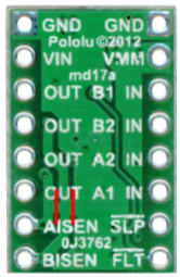
Pin Diagram
The following table lists the functions of each pin as shown in the image above.
Pin Name |
Pin Function |
GND |
Connect to ground on your breadboard |
VIN |
Connect to power from power supply to drive motors |
OUT (B1) and OUT (B2) |
Drive for motor B (connect two wires from motor) |
OUT (A1) and OUT (A2) |
Drive for motor A (connect two wires from motor) |
AISEN |
Not connected |
BISEN |
Not connected |
VMM |
Not connected |
IN (B1) and IN (B2) |
Logic control for motor B |
IN (A1) and IN (A2) |
Logic control for motor A |
SLP |
Not connected |
FLT |
Not connected |
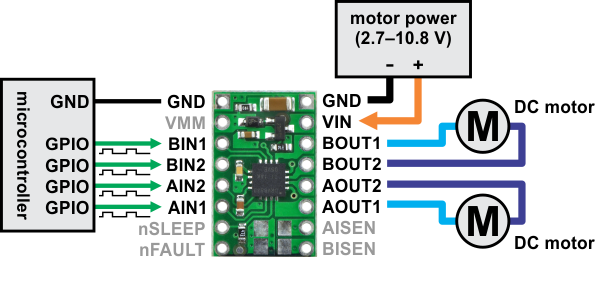
Hook Up Diagram
The following is a hook up diagram for using the MD17A that you will need for the next lesson. Note that it uses two seperate voltage supplies. One at 5V for logic provided by the USB and the other at 8V for the motors provided by your bench supply. Because the 8V could damage your logic circuit, it is imporant that this voltage is only applied to the VIN pin of the MD17A and as shown in the diagram.
Control Logic
The following table describes the control logic for the MD17A. By applying HIGH (5V) and LOW (0V) signals to the inputs you can change the direction of the motor. Note that the use of clockwise and counterclockwise is arbitrary. These merely indicate a change in direction of the motor.
IN1 |
IN2 |
Direction |
|---|---|---|
HIGH |
LOW |
Clockwise |
LOW |
HIGH |
Counterclockwise |
LOW |
LOW |
Break |
HIGH |
HIGH |
Break |