Metro Mini And Breadboard
Overview
In order to do something more interesting with your Metro Mini, you will need to connect it to a breadboard.
Power and Ground
IMPORTANT Disconnect your power supply from your breadboard if you have not already done so. Do this now!
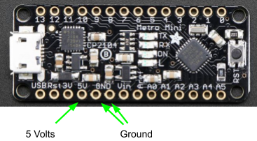
As mentioned in the previous section, the Metro Mini can supply power to your breadboard through its pins 5V and GND. This power comes from the USB that connects your Metro Mini to the computer. Inside all USB cables there are four wires. These provide power (+5V) and ground and two wires for sending and receiving data. This is why you can use your USB cable to charge your phone as well as transfer data. YOU WILL NO LONGER NEED YOUR POWER SUPPLY to supply 5V to your breadboard. Note: The Metro Mini you will be using has soldered pins unlike the one in the photos below.
Digital Pins
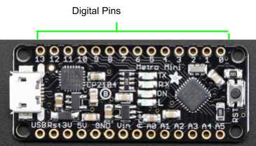
The Metro Mini has 14 digital pins (labeled 0 through 13 as shown below) that can be used to control external devices from a simple LED to a complex robot. IMPORTANT: Generally you want to avoid using pins 0 and 1 if possible. Using these pins might interfere with the programming of your device.
Exercise:
Remove all of your previous circuits before starting this step except for the wires connecting your two ground and power buses.
Insert the Metro Mini into your breadboard. Again note that the Metro Mini you are using has pins unlike the one shown in the photo.
Connect the 5V pin from your Metro Mini to the power bus (red) of your breadboard. Use a short wire.
Connect one of the GND pins from your Metro Mini to the ground bus (blue) of your breadboard. You will only need to connect one of the two GND pins.
Connect a USB Mini cable to your Metro Mini.
Measure the voltage across your power and ground bus. Write your answer in your notebook.
TEACHER CHECK _____