STEP SEVEN: Line Sensor Setup
Overview
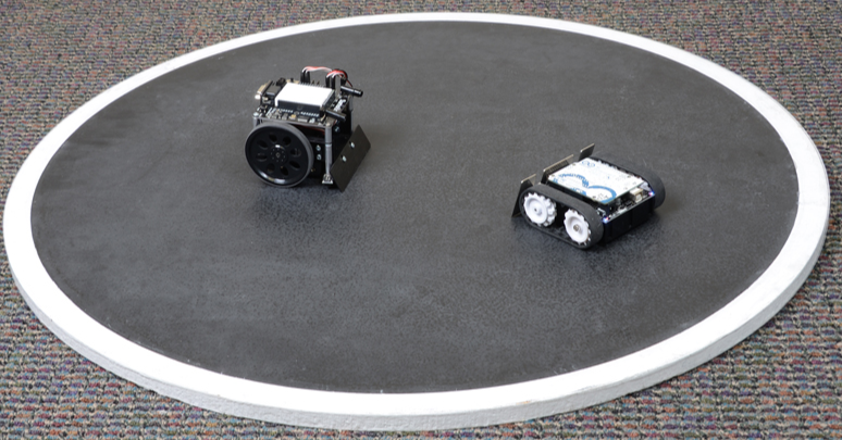
In this lesson, you will learn how to use a QTR-MD-01A Reflectance Sensor to distinguish between light and dark surfaces. Specifically, this sensor will be used to detect the white line on the outside of the sumo ring. Below is an example of the sumo ring used in this contest.
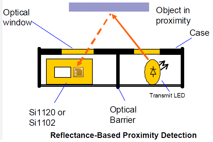
The reflectance sensor you will be using to detect lines includes both an IR emitter and IR receiver. IR refers to light in the infrared spectrum, just above red and just outside of the visible spectrum. The diagram below shows an example of how reflectance sensors work. The detector on the left side of the diagram is triggered when it detects infrared light. There is lots of infrared light in the classroom, so it will dectect that as well. It is designed to be used very close to the surface of an object, so mostly it dectects only light from the LED emitter on the right. For the sensor to dectect infrared light from the emitter, it must reflet off a surface. In the case of white, a lot of infrared light is reflected. In the case of black not enough infrared light is reflected to trigger the sensor.
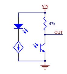
Below is a schematic diagram of a reflectance sensor. Note that it is a fairly simple device consisting of a IR LED (emitter) and an IR phototransistor (receiver). In the diagram VIN represents the 5V power supply for the circuit. Ground is clearly labeled. The most important connection on the schematic is labeled OUT. The voltage at this point on the schematic varies from 0V to 5V depending on how much IR light the receiver detects.
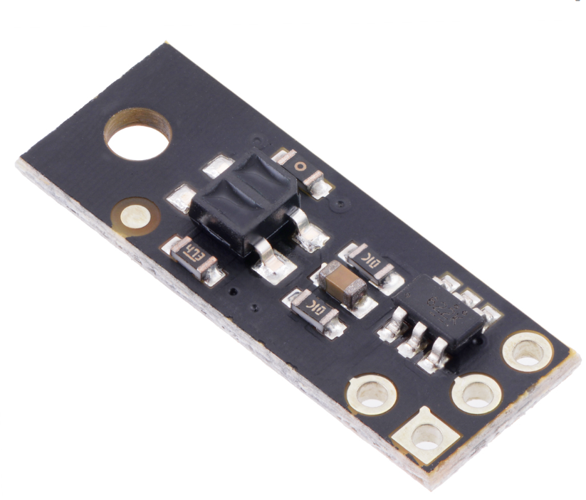
Below is an image of the QTR-MD-01A sensor you will be using. The black box with the two rectangular windows in the middle contains the IR emitter and IR receiver. Ulitmately, you will place two of these sensors on the bottom front of your robot facing down. You can check out the product page for additional information.
Specifications
The sensor has three pins for power (labeled VCC), ground (labeled GND) and signal (labeled OUT). The sensor can operate from 2.9 V to 5.5 V. The output signal (from pin OUT) is analog and should be connected to an analog port. While the sensor can detect objects from 30mm, it works optimally at 5mm.
Set up
If the three control pins (VCC, GND, OUT) are not soldered, you can solder a three pin header. Make sure to use headers from (for PCB) box (shorter) not the (for breadboard) box.
Connect the sensor to your breadboard, connecting VCC to the 5V bus and GND to ground. For initial testing, you can have your sensor facing up. Just note that it will detect IR light in the room as well as that reflected from the emitter.
Testing
Using a multimeter, test that your sensor is working correctly.
Connect the signal lead (OUT) of the sensor to the red lead of your multimeter and the black (ground) lead to ground. I recommend using the alligator leads for this.
Set the meter to measure voltage.
Power your circuit with either a USB cable or your battery supply.
Place a light or white object infront of your sensor and record the voltage.
Place a dark or black object infront of your sensor and record the voltage.
Is the voltage higher or lower with a white object infront of the sensor?
Does it matter how far away the objects are from the sensor?
Repeat your tests at approximately 5mm which is the ideal sensing range for the sensor.